I’m putting this update, in order to help myself, to reinforce my knowledge, by writing about the subject, hopefully I will have a greater understanding!
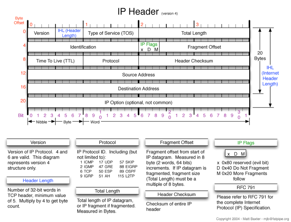 No doubt you would have come across this image for the IP header, I find this the easiest one to read, it breaks up and explains the header fields quite nicely.
So before we can analyze and understand the information in the IP header, we need to know what these fields are or represent.
Protocol Version (4 bits) – This is the first field in the IP header, which tells us which protocol is being used, predominately you will see the value of 4 in this field – which tells us that we are using IPv4.
Header Length (4 bits) – The length of the IP header. This again has a “normal” value of 5, however it can contain other values if there are any IP options present, this value will be different as the IP header length will be larger than the standard 20 bytes. The largest value the header can be is (15 * 32) 480 bits or 60 bytes and the minimum is (5 * 4) 160 bits or 20 bytes.
Type of Service or ECN (8 Bits)– This field is rarely populated, and requires both routers on the path to have the same functionality for these services to be enabled.
Total Length (16 Bits) – The total IP datagram in bytes. As the header length gives the length of the header and we have the total length of the data from this field we can calculate the length of the data field and its starting point. The maximum size of the IP datgram can be is 65535 bytes.
Identification (16 Bits) – Used to uniquelt identify the IP datagrams, this value is incremented every time an IP datagram is sent from the source to the destination, and is used for reassembly of fragmented IP datagrams.
Flags (3 bits) – The first bit is reserved. The next bit is DF – Don’t fragment, when this flag is present the IP datagram is never fragmented, if the need to fragment IP datagram arises then the datagram is dropped.
The third bit is MF – More Fragment, if this is set then it essentially means that more fragments make up the IP datagram. If this is the last fragment of an IP datagram, then this field is not sent and it then represents the last fragment.
Fragment offset (13 Bits) – If there are fragmented IP datagrams, this field contains the offset(in 8 byte units) from the start of the IP datagram, this is used for the reassembly of the fragmented IP datagrams.
Time to Live (8 Bits) – The number of hops that the IP will go through before being discarded. This value is usually dependant on the originating OS, as the packet traverses another “hop” the TTL value is decreased by one until it reaches its final destination, if the value reaches zero, then the packet is discarded.
Protocol (8 Bits) – This is the transport layer protocol, that handed the data to the IP layer.
Header Checksum (16 bits) – This value is calculated using an algorithm covering all the fields in the header. The value is calculated and stored in the header when the IP datagram is sent from the source to the destination. The destination side of this checksum is then again calculated and verified against the checksum in the header. If the value is the same then the data is not corrupt!
Source and Destination IP (32 Bits each) – These represent the values for the source and destination IP.
Options – If any IP options are present they will be represented in this field
Data – FInally we have the data field
IP Header Fundamentals
IP protocol is one of the main protocols in the TCP/IP stack. It is in the form of IP datagrams that all the TCP, UDP, ICMP and IGMP data travels over the network.
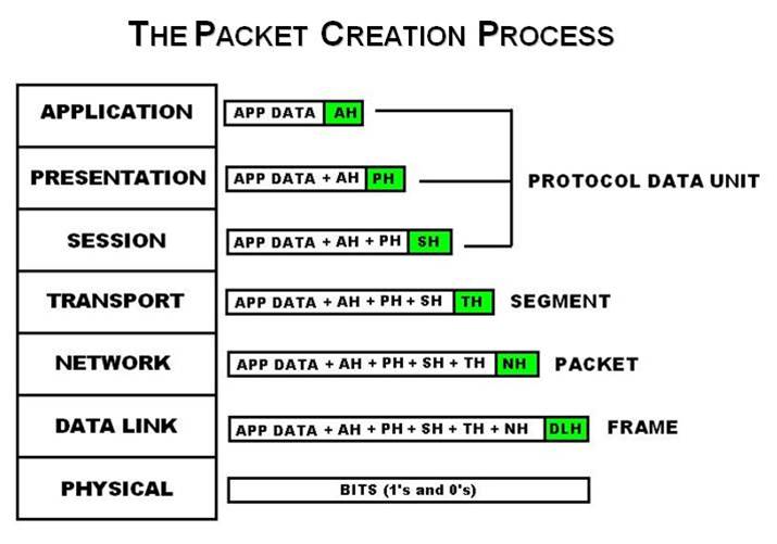
The application layer sends the data (to be transferred to the remote destination) to the transport layer. The transport layer puts in the header in the beginning and sends the complete packet (TCP-header + app-data) to the IP layer. The IP layer appends its header in front of the data received from TCP (TCP = TCP-header + app-data)
So now we have IP datagram which is IP-header + TCP-header + app-data.
The IP datagram is then passed to the ethernet layer which then adds its own header to the IP datagrams and then transmits the hole network.
On the destination host, the same process happens except in reverse, as the packet goes back through the stack to the application layer, each of the headers from the previous layer is removed.
Sounds a bit confusing? In short, each layer adds its own header….hopefully a diagram will clear up any issues.
Now that we hopefully have a basic understanding, I will add in an example which will put some of this knowledge into practice.